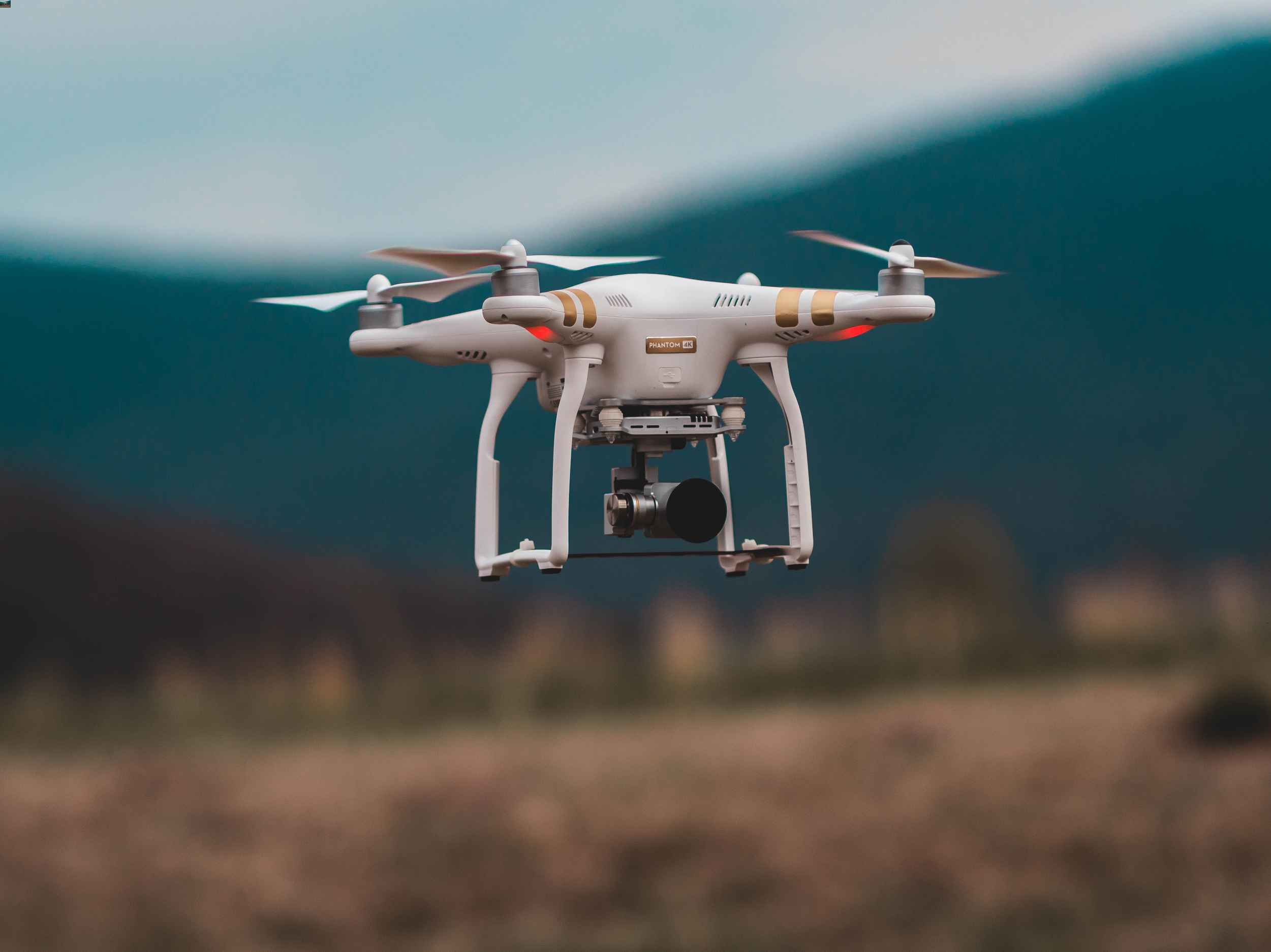
Unmanned aerial vehicles (UAVs), commonly referred to as drones, have become a prominent area of technological advancement. These aerial platforms can operate autonomously or under remote control, offering a range of applications—from surveillance and inspection to choreographed light shows and even upcoming passenger transport. Despite this growth, the drone sector still encounters regulatory challenges, operational constraints, and limited automation tools for route planning.
As drone usage expands, robust solutions for simplifying flight route planning, coverage optimization, and avoidance of restricted zones are becoming essential. SkyMap Optimizer aims to fill this need by providing a streamlined approach to mission design.
Project Purpose
The primary goal of SkyMap Optimizer is to compute efficient flight paths for multiple drones covering a given area. It operates under two main use cases:
Time Constraint: The user specifies the maximum time allowable for full coverage, prompting the tool to calculate how many drones are needed.
Drone Constraint: The user specifies how many drones are available, and the software determines the time needed for total coverage.
Beyond optimizing coverage time, SkyMap also streamlines the coordination of multiple UAVs, effectively distributing workload and avoiding redundant flight paths.
Implementation & Features
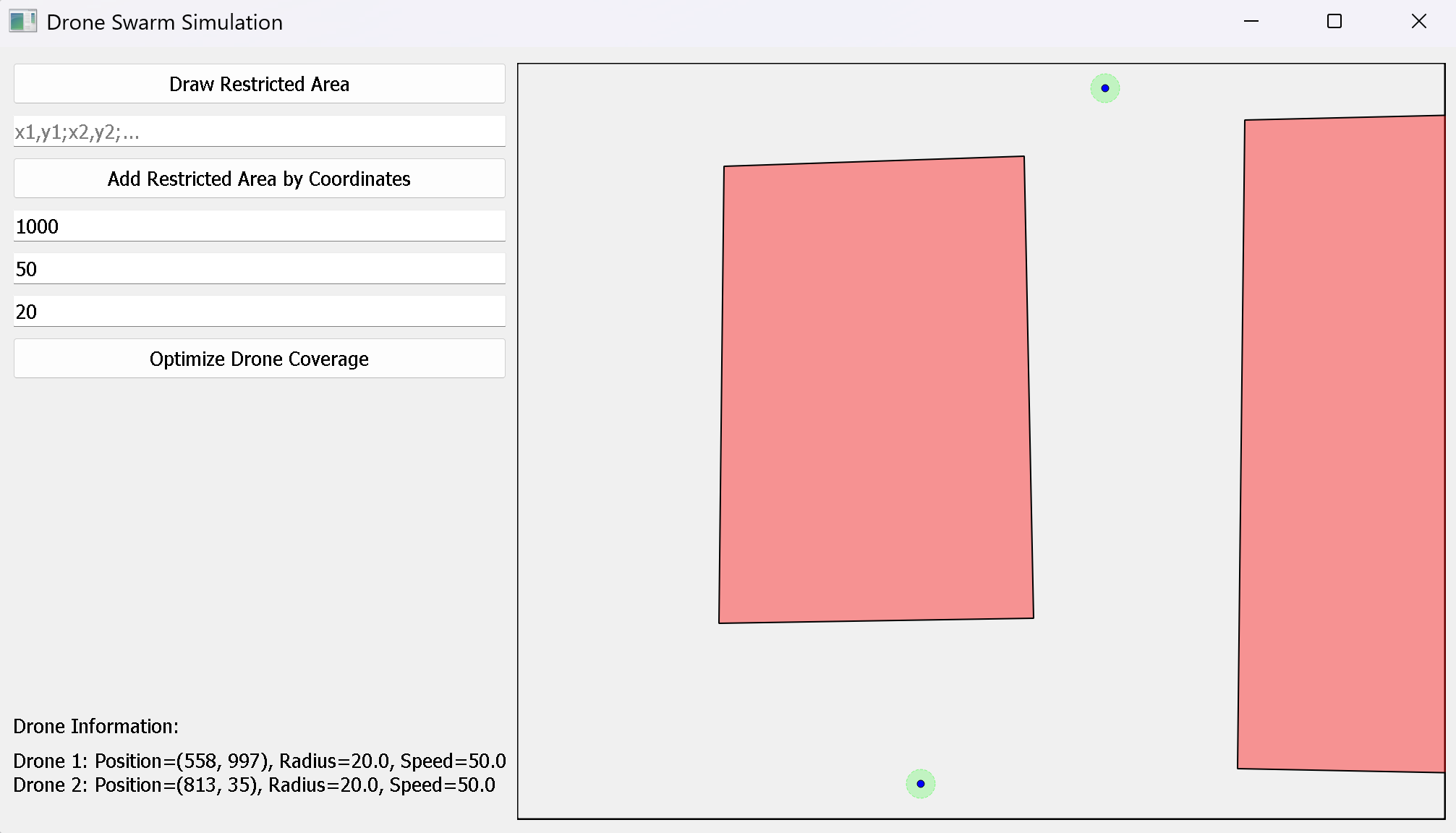
SkyMap Optimizer is written in Python and leverages a PyQt5 graphical user interface (GUI). The software discretizes the coverage area into a grid of points, automatically excluding any user‐specified restricted zones—areas that drones must avoid. Users can input drone speed, coverage radius, maximum coverage time, and other parameters to tailor the system for various scenarios, including:
Surveillance missions for urban environments.
Search and rescue operations in forests or mountainous regions.
Environmental monitoring or data gathering in designated zones.
The 2D approach suits drones flying at a constant altitude, though future versions may introduce 3D path planning. The GUI visually displays each drone’s route, ensuring transparency and allowing the user to verify that all valid points are covered.
Figure 1: The SkyMap interface displays restricted zones in red and coverage grids in white.
Multimedia Demonstrations
The video below demonstrates a simplified scenario in which two drones dynamically cover a rectangular area while avoiding restricted zones. Routes are updated in real time based on user inputs.
Limitations & Future Developments
Presently, SkyMap Optimizer works in two dimensions, reflecting a constant‐altitude flight regime. However, many real‐world operations could benefit from a 3D component, allowing altitude adjustments to circumvent obstacles or optimize coverage further. Additional areas for enhancement include:
Improved UI: Migrating from PyQt5 to a more user‐friendly framework like Windows Forms or modern web technologies.
Decentralized Coordination: Enabling drones to communicate autonomously and adapt routes mid‐flight based on battery levels or unexpected changes.
Expanded Simulation Capabilities: Incorporating weather data and dynamic obstacles for more realistic mission planning.
Conclusion
By integrating coverage optimization algorithms with a practical GUI, SkyMap Optimizer significantly eases the task of multi‐drone mission design. Whether the aim is to complete coverage in minimal time or allocate a fixed number of UAVs, the software presents an efficient and modular approach. Future iterations will continue refining user experience, flight algorithms, and real‐time adaptability, further bridging the gap between academic research and practical UAV operations.
Author: Adrià Sancho • Date: January 25, 2025
Project Files & GitHub
All files related to this project can be found in our GitHub repository (or will be added soon if not yet available). Feel free to explore, contribute, or report any issues.
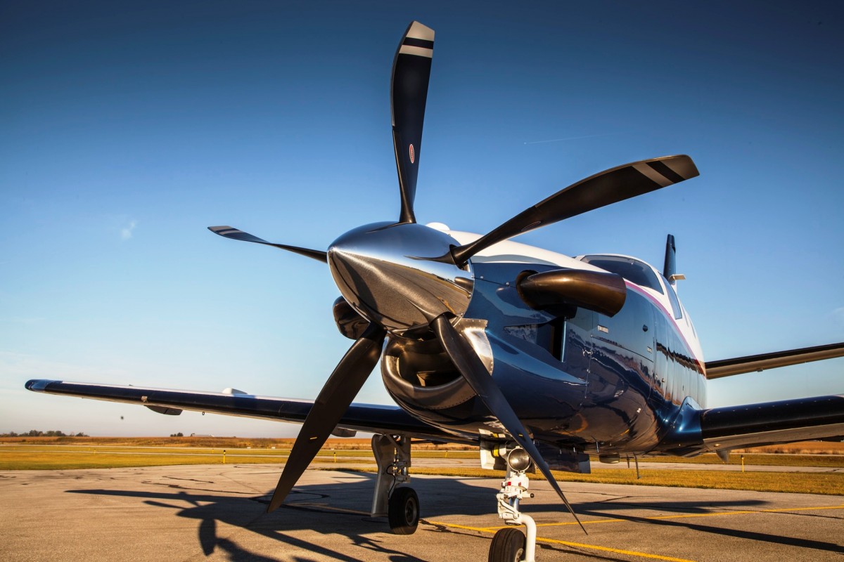
Propellers, whether used for marine or aeronautical applications, present intricate aerodynamic and structural considerations. Early aviation pioneers utilized propellers for powered flight, and modern variations continue to propel both manned and unmanned aircraft. Despite decades of research, no single standardized method fully captures the complexities of propeller design, which often depend on blade number, chord distribution, twist angles, and tip speeds.
For small RC aircraft and low‐speed drones, propeller selection can significantly influence performance, noise levels, and flight stability. This project employs Ansys Fluent (Student Edition) to systematically analyze different propeller geometries, examining how design changes impact efficiency and thrust generation.
Project Purpose
The study focuses on how blade count, radius, and torsion affect overall propeller performance. Key factors include:
Blade Count: Increasing the number of blades can boost thrust but may exacerbate wake interference.
Radius: A larger radius offers more lift area but increases tip velocities, risking transonic or supersonic flow regimes if RPMs are high.
Blade Twist: Properly tuning the pitch or twist distribution ensures an effective angle of attack along the blade span.
By validating these parameters in a controlled simulation environment, the project aims to inform the design of a future low‐speed RC aircraft, ensuring optimal thrust generation without excessive noise or structural load.
Software & Methodology
Ansys Fluent was selected due to its user‐friendly interface and robust solver framework. Although open‐source platforms like OpenFOAM were considered, the intuitive setup in Fluent allowed faster iteration. Each propeller design is imported into a rotating reference frame, with the following conditions:
Low‐Speed Flow: Typically under 20 m/s for the incoming velocity, with Mach < 0.3.
Diameter ~10 cm: Representative of small electric‐powered drones or RC aircraft.
8000 RPM: Chosen to reflect moderate rotational speeds for small propellers.
RANS Turbulence: A k‐ε model to approximate turbulent effects on the blade surfaces.
Meshing strategies vary from coarse initial runs to refined boundary layers near blade tips. The solver computes thrust, torque, and efficiency under steady‐state assumptions, guiding subsequent design choices.
Future Plans
After initial simulations validate the feasibility of each geometry, multiple designs will be compared, highlighting trade‐offs in thrust, noise, and structural load. Possible future lines of inquiry include:
Toroidal Propellers: Investigating novel ring‐shaped blade designs for potential noise reduction and efficiency gains.
Ducted Propellers: Exploring shrouded configurations that may enhance static thrust, especially in hovering or low‐speed conditions.
Time‐Accurate Analysis: Transitioning from steady‐state RANS to transient simulations to capture wake interactions more precisely.
Ultimately, the findings will guide a future RC aircraft build, ensuring propeller choice aligns with performance and operational constraints.
Conclusion
Propeller design remains an ongoing challenge, particularly at smaller scales where manufacturing constraints, noise considerations, and aerodynamic efficiency must all be balanced. By harnessing Ansys Fluent, this project provides insight into how minor adjustments—such as adding a blade or altering the tip radius—can significantly alter thrust and efficiency. As the simulations progress and more advanced geometries are tested, these results will serve as a blueprint for engineering an effective, low‐speed propeller configuration suitable for small drones or RC aircraft.
Author: Adrià Sancho • Date: January 25, 2025
Project Files & GitHub
All files related to this project can be found in our GitHub repository (or will be added soon if not yet available). Feel free to explore, contribute, or report any issues.
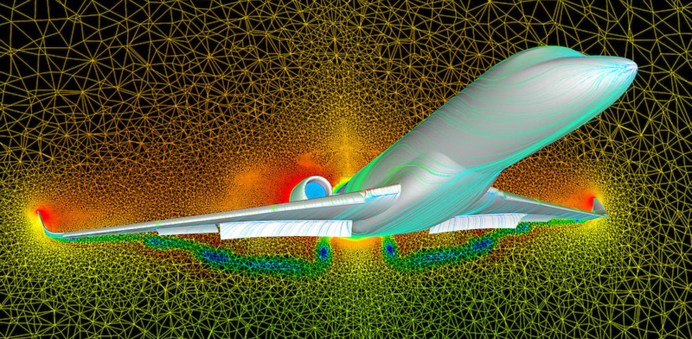
Commercial CFD platforms can handle an array of complex physics, from turbulence modeling to multiphase flows. However, building a custom solver from scratch offers profound insight into the fundamental equations and numerical methods under the hood of these established tools. This project focuses on a potential flow solver in MATLAB, facilitating a simplified—but instructive—way to explore aerodynamic phenomena around 2D bodies.
Potential flow theory assumes an inviscid, irrotational flow field, making it impossible to compute drag or account for flow separation. Still, it provides valid estimates of lift for cambered bodies and captures how velocity and pressure fields develop around streamlined shapes.
Project Background
Initially, this custom CFD tool was designed as part of a fluid mechanics final project by Hugo García. Following the course’s conclusion, both Hugo and Adrià Sancho sought to enhance it further—transitioning from a quick Python prototype to a more optimized MATLAB implementation, owing to the latter’s suitability for matrix operations and numerical solvers. By iterating on mesh generation, boundary conditions, and visualization routines, the software evolved into a standalone solver for 2D inviscid flows.
Implementation & Capabilities
The solver is built upon the following core elements:
Shape Definition: Users can input a function describing the body’s geometry. Predefined shapes include NACA airfoil approximations and basic curves like circles.
Mesh Construction: A boundary‐fitted or structured mesh is generated, categorizing points as either solid or fluid nodes.
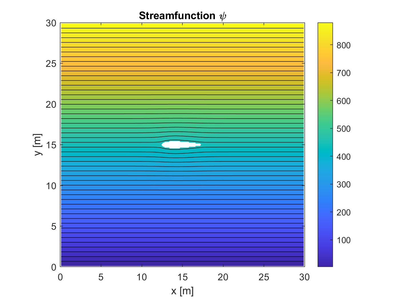
Finite‐Difference Solver: Potential flow equations are solved via central differencing, yielding velocity potential and streamfunction fields.
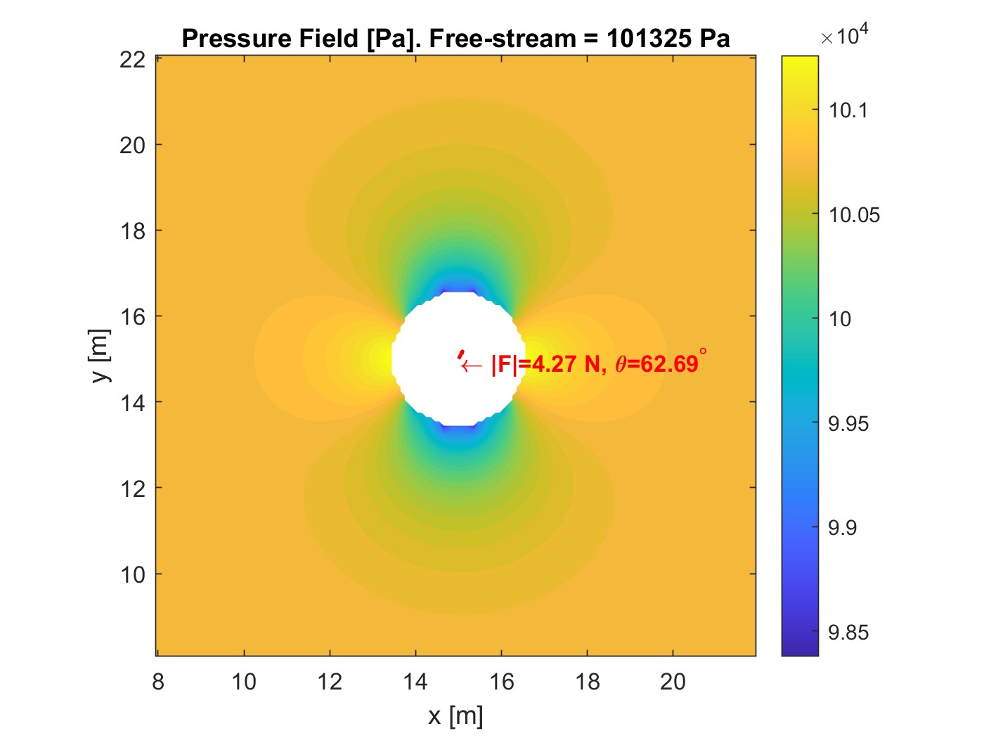
Data Visualization: Results include streamline plots, velocity magnitudes, and pressure distributions around the body.
Figure 1: Stream function through streamlined body.
Figure 2: Pressure contour visualization in a blunt body.
While potential flow theory cannot predict drag, it effectively demonstrates how subtle alterations in geometry (such as camber or thickness) alter local pressure. Additionally, symmetrical shapes produce near‐zero net lift (under idealized conditions), which can validate the solver if meshing and boundary conditions are implemented correctly.
Limitations & Future Improvements
Because this tool models an inviscid, irrotational flow, real‐world effects like boundary layers, turbulent separation, and vortex shedding lie beyond its scope. Nevertheless, the solver’s framework can be extended or coupled with additional modules to capture more phenomena:
Boundary‐Layer Approaches: Incorporating approximate methods like Falkner‐Skan to account for viscosity near surfaces.
Higher‐Order Schemes: Exploring more advanced finite‐difference or finite‐volume strategies to reduce numerical error.
3D Expansion: Evolving from 2D cross‐sections to fully three‐dimensional geometry for more realistic modeling.
Validation: Comparing results against commercial solvers such as Ansys Fluent or open‐source alternatives like OpenFOAM for benchmark cases.
Conclusion
By focusing on potential flow, this custom solver offers an accessible entry point into aerodynamic simulation. Despite inherent limitations—such as an inability to compute drag—it imparts a foundational understanding of how fluid velocities and pressures develop around shaped bodies. With plans for further refinement and integration of viscous modeling, the tool stands poised to serve as a stepping stone toward more advanced CFD applications, bridging classroom theory and practical numerical experimentation.
Authors: Adrià Sancho & Hugo García • Date: January 25, 2025
Project Files & GitHub
All files related to this project can be found in our GitHub repository (or will be added soon if not yet available). Feel free to explore, contribute, or report any issues.